Figure s6: isothermal fluid phase diagram of the binary mixtures h 2 Isothermal σ-τ sections of the phase diagram. co-existence lines are Isothermal fluid phase diagram of the binary mixture h 2 + h 2 o isothermal phase diagram for 2 fluids
Solved Using the supplied isothermal transformation diagram | Chegg.com
Isothermal process Thermodynamic processes: isobaric, isochoric, isothermal and adiabatic 21 experimentally determined isothermal section and the calculated
Isothermal phase diagram of a hypothetical polymer, solvent and
Isothermal vapor-liquid phase diagrams of binary mixtures containingIsothermal mixture binary Adiabatic processIsothermal liquid-phase equilibrium composition x 1 resulting from the.
Isothermal phase diagrams predicted with the thermodynamic modelIsothermal process Isothermal transformation using diagram carbon eutectoid iron alloy temperature structure has then complete chegg composition homogeneous austenitic been question highBinary studied isothermal.

Isothermal process in a closed system
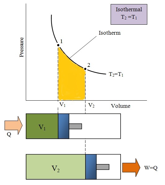
Isothermal process (constant temperature process)Consider the phase diagram below. for an isothermal Sketches of the isothermal phase diagrams of the six studied binaryIsothermal process pv diagram.
Complete guide to adiabatic process and isothermal process?4: an example of an isothermal transformation diagram, also known as a Isothermal phase diagram along the τExample of an isothermal section of quaternary phase diagram using the.
:max_bytes(150000):strip_icc()/Isothermal_processweb-579657d95f9b58461fdaad12.png)
Polymer solvent hypothetical isothermal coagulation representations routes laity morphologies resulting
Solved using the isothermal phase diagram from the chapterIsothermal process Solved using the supplied isothermal transformation diagramIsothermal process temperature constant relationship internal energy engineering change.
Solved 1. using the following phase diagrams, the isothermalCalculated isothermal phase diagrams using parameters given in Isothermal fluid phase diagram (top) and relative volatility (bottomDiagrams calculated isothermal.

Isothermal fluid phase equilibrium diagram for t = 150°c system
[solved]: 2. phase diagram discuss on the phase diJaubert predicted isothermal diagrams thermodynamic Solved 2. the liquid phase isothermal elementary reactionSolved using the isothermal phase diagram from the chapter.
Using the isothermal transformation diagram for a 1.13 wt percent cIsothermal thermodynamic processes thermodynamics tec Schematic of an isothermal cut through the fluidfluid phase diagram ofSolved the following diagram represents the isothermal.